
Smart Lock Installation: The Complete Step-by-Step Engineering and Setup Guide
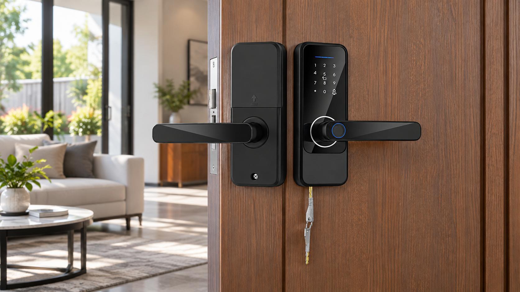
Upgrading your entry door hardware transforms everyday convenience, but a successful smart lock installation demands mechanical precision before digital pairing can even begin. Whether you manage a boutique hotel or secure a private apartment, treating an electronic door lock merely as a gadget rather than an integrated mechanical assembly often leads to premature motor burnout, latch binding, and compromised physical defense. Proper preparation prevents the frustrating cycle of alignment errors that leave doors unlatched or deadbolts jammed.
Intelligent door locks vary widely in design. Some models pair physical deadbolts with biometric sensors and cloud access controllers, while others focus on simpler keypad or card access without remote connectivity. When you tackle a smart lock installation project, you may be replacing conventional tumblers with a motorized latch mechanism and data wiring harnesses, depending on the model you choose. Taking a systematic approach to door geometry, spindle tolerances, and strike alignment helps your new digital access system operate smoothly for years to come.
1. Pre-Installation Door Audit: Assessing Mechanical Compatibility
1.1 Door Thickness and Stile Width Measurements
Before removing existing hardware, verify that the physical door dimensions match your new lock hardware specifications. Different smart lock models support different door thickness ranges, so consult the installation template provided with your specific unit. Installing a lock on a door outside its supported range leaves spindle shafts either too short to engage the internal clutch or so long that they compress the motorized gearbox.
Measure the door stile, which is the vertical framing section running along the outer edge of the door. If your door features decorative glass inserts or recessed panels, the lock escutcheon must sit completely flush against the flat stile face without overlapping decorative molding. Check the installation template to confirm that your door provides adequate flat surface area around the planned mounting location before drilling.
1.2 Backset and Bore Hole Geometry
The backset represents the exact distance from the outer door edge to the center point of the primary bore hole. Many North American residential doors use a backset of either 60 mm (2-3/8 inches) or 70 mm (2-3/4 inches), though this is not a universal standard across all regions or lock types. Using an incorrect backset forces the faceplate to tilt, exerting excessive lateral pressure on the latch bolt and preventing it from extending fully into the strike pocket.
Some common residential hardware uses a cross-bore hole through the door face measuring around 54 mm (2-1/8 inches), alongside a smaller 25 mm edge-bore hole that accepts the latch cylinder, though these figures can differ by manufacturer and region. Always confirm the exact bore dimensions against your lock's installation template before drilling. If your previous lock used non-standard commercial architectural fittings, you may need a wood chisel or hole saw jig to enlarge the opening. Avoid forcing the panels into tight holes; pinched or abraded wiring can be damaged and may cause electrical faults.
1.3 Mortise Pocket vs Cylindrical Latch Verification
Electronic locks may use either a cylindrical latch chassis or a mortise lock body, depending on the model and the door it is designed for. Cylindrical deadbolts fit into simple intersecting cylindrical bores, making them straightforward for standard residential doors. Mortise locks, by contrast, require an internal rectangular cavity cut into the core of the door edge, with exact dimensions set by the specific lock model and its installation template.
Separately, either chassis type may offer single-point or multipoint locking, depending on the model. Single-point designs extend one latch or bolt into the frame, while multipoint systems engage several locking points along the door edge for added resistance to forced entry. The locking configuration is a design choice independent of whether the chassis is cylindrical or mortise.
| Lock Chassis Type | Door Cutout Requirement | Typical Security Application | Best Application Setting |
|---|---|---|---|
| Cylindrical Deadbolt | Dual intersecting cylindrical bores, sized per lock template | Standard residential security | Single-family homes and retrofits |
| Mortise Lock Body | Rectangular edge pocket, depth and height per lock template | Residential and commercial applications | Commercial buildings, hotels, and luxury apartments |
| Narrow Stile Mortise | Shallow profile rectangular cavity, sized per lock template | Medium commercial security | Aluminum profile and framed glass doors |
Identifying your door core composition determines how much modification will be necessary. Solid timber doors accept fresh chiseling smoothly, but hollow-core doors lack structural backing for heavy commercial mortise chassis. If retrofitting a metal security door, preexisting internal bracket welds can obstruct non-original mortise depths, requiring precise dimensional matching before purchasing replacement hardware.
2. Essential Tools and Hardware Preparation
2.1 Essential Hand and Power Tool Checklist
Executing a clean hardware conversion requires a balance between mechanical precision and delicate torque control. While heavy carpentry tools help cut clean mortise pockets, over-torquing structural screws during final assembly can warp sensitive escutcheons or strip fastener threads. Assemble your tools prior to loosening the first exterior screw on your existing entryway.
- Phillips head screwdrivers (PH1 and PH2) for driving mechanical fasteners without stripping screw heads
- Digital caliper or steel measuring tape to verify backset, stile depth, and door leaf thickness
- Sharp wood chisels (1/2 inch and 1 inch) along with a mallet for clearing mortise corners
- Level vial to ensure vertical escutcheon alignment before tightening exterior connecting bolts
- Painter masking tape to protect door veneer finishes during boring and marking procedures
Avoid using high-RPM impact drivers when securing the interior mounting plate or battery housing unless your lock's manual specifies otherwise. A dedicated manual screwdriver provides the tactile feedback necessary to gauge thread engagement and avoid overtightening, which helps prevent stripped threads or damaged mounting hardware.
2.2 Unboxing and Hardware Component Inspection
Carefully unpack the hardware kit and lay out each sub-assembly on a flat, padded work surface to prevent scratching the powder-coated or anodized finish. Check that the package contains the front escutcheon with keypad, the interior handle assembly, the mortise lock body, rubber weatherproofing gaskets, drive spindles, connecting screw pairs, and physical backup keys. Verify that delicate silicone-sheathed data cables are free from kinks or exposed copper strands.
Match your door thickness against the included fastener packet. Most manufacturers supply two or three distinct screw lengths and spindle segments to accommodate varying door thicknesses. Selecting fasteners that are too long will bottom out before clamping down, while excessively short screws will grip only one or two threads, tearing out under moderate door slamming forces.
2.3 Handle Handing and Direction Reversal
Door handing determines whether the lock handle swings left or right to clear the door jamb without trapping knuckles. Examine your door swing from the exterior: if the hinges are on your left, you have a left-handed door configuration, and if they are on your right, the door is right-handed.
Whether your lock's handle can be reversed, and how, depends entirely on its internal design. Some digital locks feature reversible clutch assemblies, while others ship as handed products with no field-reversal option. Check your lock's installation manual to confirm whether handle reversal is supported and to follow the exact procedure for your model before mounting the hardware.
3. Step-by-Step Physical Smart Lock Installation
3.1 Installing the Lock Mortise Body and Cylinder
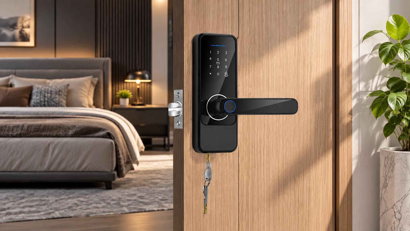
Begin physical assembly by sliding the mortise lock body into the prepared pocket along the door edge. The beveled latch bolt must face the strike plate on the door frame, allowing the latch to depress smoothly as the door swings shut. Follow the manufacturer's installation instructions for your specific lock model, as internal mechanisms and fastening methods vary between designs.
For locks that use a separate mechanical cylinder, refer to the installation template to determine the proper insertion depth and orientation. Secure all faceplate fasteners according to the torque specifications in the manual. Test manual key operation immediately to ensure the deadbolt throws and retracts smoothly without friction.
3.2 Spindle Sizing and Cable Routing Through the Door Face
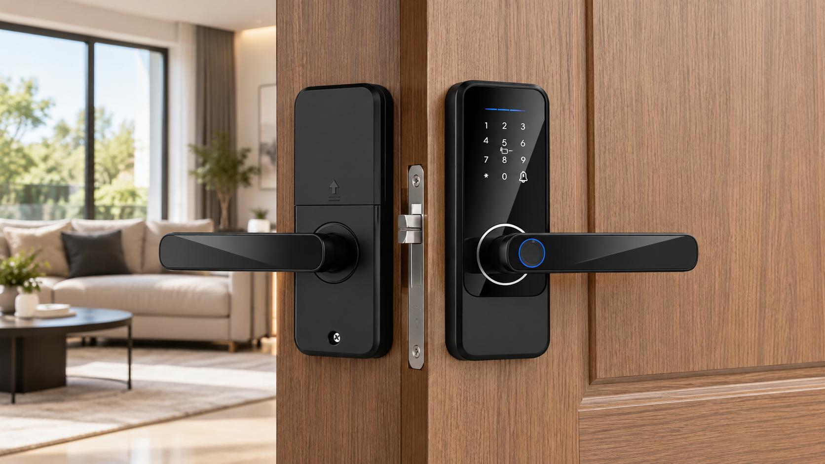
The central square drive spindle transfers mechanical rotation from the exterior and interior handles directly into the mortise hub. Refer to your lock's installation guide to identify the correct spindle length for your measured door thickness and to understand the proper assembly sequence for compression springs and retaining hardware.
Carefully guide the electronic data ribbon through the designated pass-through hole, following the routing diagram in your installation manual. Never route wires through the same borehole occupied by the moving drive spindle. Improper cable routing can lead to wire damage from mechanical friction, causing intermittent system failures or complete loss of electronic functionality.
3.3 Securing the Exterior Escutcheon and Interior Mounting Plate
Position the exterior escutcheon firmly against the outside of the door, ensuring any rubber weather-seal gasket sits seated in its perimeter channel. Pass the threaded metal standoffs through the pre-drilled cylindrical holes, supporting the front panel with one hand to keep it from slipping and scratching the exterior finish.
From the interior side, take the stamped steel mounting plate and thread the data wire harness through its central rectangular cutout. Align the plate mounting holes with the exterior standoffs. Thread the primary machine screws by hand for several turns to confirm proper thread alignment before tightening them down evenly with a hand screwdriver, checking alignment with a spirit level before the final turns.
3.4 Connecting the Interior Unit and Battery Compartment
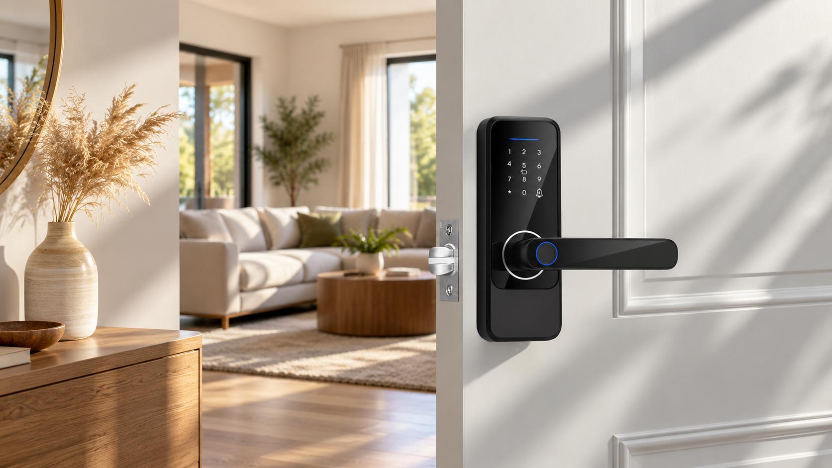
Bring the interior handle assembly close to the mounting plate. Connect the multi-pin electronic connector from the front escutcheon into the receiver port on the rear circuit board, following the keying and orientation guidance in your installation manual. These micro-connectors are keyed with directional grooves; force should never be applied, since bending a single pin can disable touch keypads or fingerprint communication entirely.
Tuck excess cable neatly into the hollow cavity of the door or behind the recess in the rear plate. Position the interior panel over the mounting plate, ensuring the thumb-turn shaft aligns with the deadbolt tailpiece. Fasten the interior housing using the provided short machine screws, install four AA alkaline batteries, and verify that the system powers on according to the startup sequence described in your manual.
4. Frame Strike Plate Realignment and Mechanical Calibration
4.1 Door Jamb Strike Box Depth and Alignment
Improper strike alignment causes many post-installation failures in digital lock systems. When a standard mechanical lock requires a firm pull to latch, people naturally compensate by applying shoulder pressure against the door. An automated electronic smart lock motor, however, generates finite torque and will stall if the deadbolt rubs against the jamb pocket during extension.
Verify that the mortise cavity inside the door frame jamb provides adequate depth for full deadbolt extension, using the dimensions specified in your lock's installation template. If the deadbolt cannot reach full extension, enlarge the jamb pocket using the tool and method recommended in your lock's manual until the bolt seats with the clearance the template specifies.
4.2 Manual Deadbolt and Lever Engagement Testing
Perform a comprehensive tactile calibration before closing the door with the smart lock engaged. While the door remains wide open, operate the interior thumb-turn or manual controls back and forth. The deadbolt should glide effortlessly without grinding, clicking harshly, or binding against the internal mortise guide plates.
- Pull the door closed slowly while observing the horizontal alignment between the latch bolt and the strike plate hole
- Throw the deadbolt while the door is shut; the bolt should extend fully without requiring you to push or pull the door leaf
- Test the interior handle or thumb-turn to confirm smooth retraction of the locking mechanism
- Turn the mechanical emergency key from the exterior side to confirm unpowered physical bypass capability
If the deadbolt binds when the door is shut, inspect the weatherstripping along the door frame. Thick rubber seals can push the door leaf outward, misaligning the deadbolt with the strike opening. Consult your lock's installation template for the permitted strike plate adjustment range, and readjust frame stop molding as needed to resolve friction issues and relieve stress on the internal motor gearbox.
5. Digital Configuration and Access Setup
5.1 Pairing via Tuya or TTLock Management Platforms
Once physical mechanical alignment is validated, initialize the digital access management platform. Hardware solutions such as the S810 can interface with management applications like Tuya Smart or TTLock. Download your chosen application, enable mobile Bluetooth, and follow the pairing instructions in your lock's manual to wake the system broadcast mode.
Tap the add device icon within the application dashboard. The smartphone detects the nearby unconfigured lock module within seconds. Assign a master administrator account and verify the system clock to ensure accurate historical entry timestamps. If your lock version supports remote access features, follow the manufacturer's instructions for connecting to your network infrastructure.
5.2 Biometric Enrollment and Virtual Passcode Configuration
Biometric registration requires proper finger placement technique. When enrolling fingerprints onto the semiconductor scanner, lift and press your fingertip multiple times, angling the core, outer edges, and upper whorl across the glass surface. This multi-angle mapping helps maintain consistent recognition even if a finger taps the scanner off-center.
When setting up numerical PIN codes, check whether your lock supports a virtual password masking feature. This feature, where available, allows users to input arbitrary numbers before and after the actual master code, such as entering 3819 plus [your code] plus 7721. Choose a unique, hard-to-guess code rather than a simple or sequential number, since the masking digits only obscure the sequence from onlookers rather than strengthen a weak code itself. A bystander attempting shoulder-surfing cannot easily distinguish the authentic access sequence from the surrounding numerical noise, which helps maintain credential confidentiality in shared corridors.
5.3 RFID Key Card and Emergency Physical Key Testing
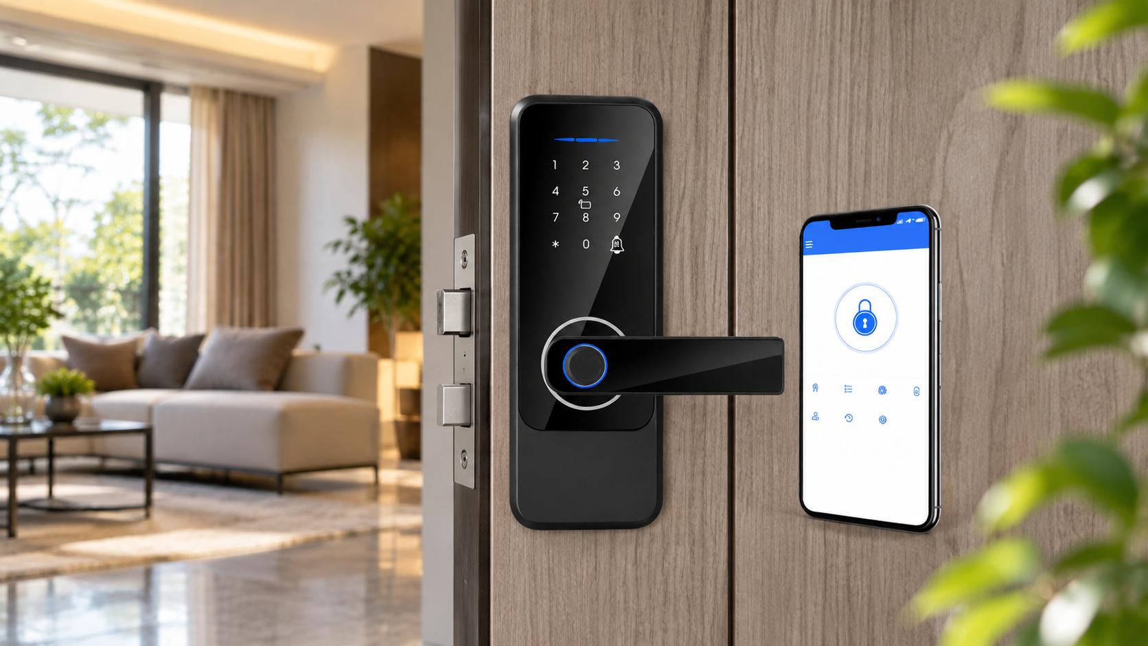
Pair any included RFID cards by following the card management steps described in your lock's manual, since the enrollment menu location and the card-reading gesture can differ between app versions and hardware revisions. The lock assigns a unique identifier token to each card, allowing property managers to revoke lost cards individually without resetting user codes or replacing physical lock cylinders.
Finally, test the exterior emergency recovery interfaces before closing the project. Locate the mechanical keyhole as described in your lock's manual, since its position and any protective cover vary by model. Insert the physical key to confirm manual deadbolt rotation, and connect a portable power bank to the emergency Type-C port to verify temporary power supply during battery depletion. Note that emergency power provides temporary electrical supply; all normal authentication and access controls remain in effect.
6. Commercial and Multi-Tenant Deployment Considerations
6.1 Standardizing Door Prep Across Apartment Blocks
Large-scale deployments in multi-family developments require rigid standardization across door preparations. When dealing with dozens or hundreds of entryways, manual chiseling introduces human error that results in misaligned strike plates and varied latch tolerances. Professional installation crews rely on metal clamping router jigs to mill out exact mortise pockets and surface escutcheon holes in minutes.
Standardized hardware simplifies long-term facility maintenance. For enterprise access hardware, our team at SUMMAO manufactures access solutions such as the Digital WiFi Smart Lock S810, which combines an aluminum alloy body with a Grade C lock cylinder as specified by the manufacturer to support large-scale retrofitting. Utilizing factory-calibrated hole templates helps maintain consistent hardware performance and reduces maintenance overhead across extensive residential portfolios.
When working with doors that have specific fire-rating or security certifications, modifications must only be performed when permitted by the door assembly certification, approved hardware listings, and applicable local fire safety regulations. Unauthorized alterations can void certifications and compromise life-safety systems. Consult with qualified personnel familiar with the relevant codes and certification requirements before modifying any certified door assembly.
6.2 Power Management and Fail-Safe Protocols
Commercial access hardware demands rigorous battery management strategies to prevent unexpected tenant lockouts. According to the S810 product specifications, the lock is powered by four AA alkaline batteries.
- Many smart locks provide low-voltage reminders when battery capacity approaches depletion
- Cloud management software, where supported, may flag battery status on administrative dashboards during routine syncs
- Non-volatile internal memory in quality locks retains user credentials, access permissions, and logs during power loss
- Emergency USB Type-C external power, where provided, supplies temporary electrical power for lock operation when internal batteries are depleted
Avoid mixing aged batteries with fresh ones, and avoid non-alkaline zinc-carbon cells, which drop operating voltage rapidly under inductive motor loads. Alkaline chemistry supports a steadier current supply to the motorized latch. If the bolt sticks or feels stiff during cold weather, treat that as a separate door alignment issue and check the strike plate and weatherstripping rather than assuming the battery is the cause.
7. Frequently Asked Questions
How do I measure my door to ensure a smart lock will fit before drilling?
Measure three core dimensions using a precision ruler: door thickness, backset, and stile width. Check door thickness along the open edge and compare it to the specifications in your lock's installation manual. Next, measure the backset from the outer edge to the center of your primary handle hole, and compare it against the lock's supported backset options. Finally, verify that the flat stile area matches the installation template requirements so the lock escutcheon sits flat without hitting decorative glass moldings or other door features.
Why is the smart lock latch sticking or failing to lock automatically?
Latch binding almost always stems from mechanical misalignment between the lock deadbolt and the frame strike plate pocket. When seasonal humidity shifts a wooden door leaf, the deadbolt can scrape against the metal strike rim, creating friction that overpowers the small internal drive motor. Check whether the lock operates smoothly while the door is held wide open. If it does, adjust the strike box opening and strike plate position according to the installation template until the bolt glides freely when shut.
Can smart locks be installed on exterior metal or UPVC doors?
Yes, smart locks can be installed on metal and UPVC doors, but the process requires specialized hardware considerations. UPVC doors frequently utilize complex multipoint locking linkages driven by Euro-profile cylinders, requiring an electronic lock chassis designed specifically for narrow stiles. Hollow insulated metal doors often need particular fasteners, spacers, or existing internal reinforcement to support the lock securely; check the door's preparation and use only the fastening method and hardware specified for your specific lock and door combination, since the wrong approach can damage the door or leave the lock insecure.
What should I do if the smart lock battery drains completely while I am locked outside?
If the internal AA alkaline cells drain fully, you can regain entry using two secondary access methods built into the exterior escutcheon. You can insert the physical mechanical backup key into the concealed keyway to rotate the deadbolt manually. Alternatively, if your lock is equipped with an emergency Type-C port, connect a portable power bank using a standard cable to supply temporary power to the keypad and fingerprint sensor. Normal authentication procedures apply even when using emergency power.
Is professional installation necessary, or can this be completed as a DIY project?
Homeowners with basic carpentry experience can often complete a standard retrofit using basic hand tools, provided the existing door bore holes align with the replacement chassis. The time required varies considerably depending on the lock model, the amount of existing door preparation, and the installer's experience. However, if your entry door lacks existing cutouts or requires a deep mortise pocket carved into a solid hardwood core, hiring an experienced architectural locksmith is recommended to avoid costly door slab damage.
8. Conclusion: Ensuring Long-Term Security and Reliable Operation
8.1 Core Installation Takeaways
A trouble-free smart lock installation depends on mechanical alignment rather than electronic settings alone. The best software and biometric sensors cannot compensate for a misaligned strike plate or a pinched internal ribbon cable. By verifying door dimensions against installation templates, routing data wires safely past moving mechanical components, and preparing clean frame pockets, you establish a stable foundation for automated access control.
Take the time to evaluate door balance before locking down hardware fasteners. A door leaf that hangs plumb and latches without manual pushing protects the motorized gearbox from unnecessary mechanical drag. When physical components move freely, the digital locking system delivers effortless daily entry, reliable guest passcodes, and peace of mind.
8.2 Pre-Operation Verification Checklist
Before relying on your new lock for everyday security, run through a final functional inspection. Confirm that each mechanical and electronic pathway operates without hesitation while you remain safely inside the property:
- Verify that the deadbolt extends and retracts with minimal resistance while the door is closed and latched
- Ensure the data ribbon sits clear of moving spindles and mounting screws without tension
- Confirm that the mechanical key turns smoothly inside the lock cylinder
- Test registered fingerprints, numeric PIN codes, and RFID cards to confirm reliable recognition
- Check that the mobile application, where supported, displays real-time battery status and logs test unlock events accurately
Completing your smart lock installation with careful mechanical adjustments supports reliable keyless entry for private residences, commercial facilities, and short-term rental properties alike.
SUBSCRIBE
INQUIRY